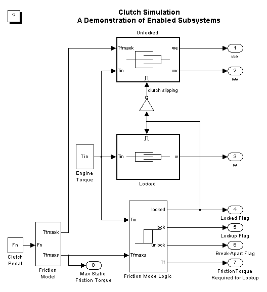
The clutch system in this example consists of two plates that transmit torque between the engine and transmission. There are two distinct modes of operation; slipping, where the two plates have differing angular velocities; and lockup, where the two plates rotate together. Handling the transition between these two modes presents a modeling challenge. As the system loses a degree of freedom upon lockup, the transmitted torque goes through a step discontinuity. The magnitude of the torque drops from the maximum value supported by the friction capacity to a value that is necessary to keep the two halves of the system spinning at the same rate. The reverse transition, break-apart, as the torque transmitted by the clutch plates exceeds the friction capacity, is also challenging.
There are two methods for solving this type of problem:
Simulink can model either method. In this example, we describe a simulation for the second method. In the second method, switching between two dynamic models must be performed with care to ensure that the initialized states of the new model match the state values immediately prior to the switch. In either approach, Simulink facilitates accurate simulation due to its ability to recognize the precise moments at which transitions between lockup and slipping occur.
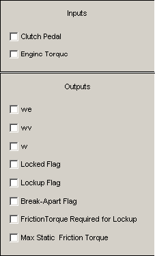
In the demonstration, we use enabled subsystems to build the clutch model. Two enabled subsystems model the clutch dynamics in either the locked or unlocked position. After running the simulation, a GUI opens. Checking any of the boxes on the GUI produces a plot of any of the selected variables (versus time).
A detailed review of the equations used in this design can be found in the white paper Using Simulink and Stateflow for Automotive Examples. Please note that this paper is based on an older version of Simulink and does not use all the newest block diagramming features in the current version of Simulink.