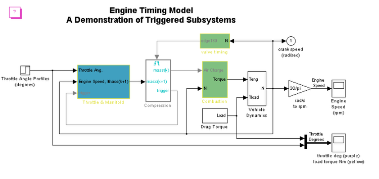
This demonstration shows how to use Triggered subsystems to model engine timing. Different subsystems in the diagram model the mathematical representation of various automotive systems, including the following:
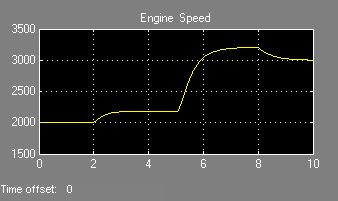
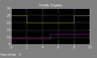
The valve timing subsystem generates a signal that triggers the Compression subsystem twice per revolution of the crank (calculated from the crank speed.) A throttle schedule (in angles) from the block labeled "Throttle Angle Profiles" on the left side of the diagram drives the simulation. After you run the simulation, the Scopes show the engine speed and the throttle angle compared to the load torque.
The model sldemo_enginewc adds an additional triggered subsystem that provides closed-loop engine speed control via a throttle actuator. These models can be used as standalone engine simulations or within a larger system model, such as an integrated vehicle and powertrain simulation, in the development of a traction control system.
The model is based on published results by Crossley and Cook (1991) and describes the simulation of a four cylinder spark ignition internal combustion engine. The Crossley and Cook work also shows how a simulation based on this model was validated against dynamometer test data.
A detailed review of the equations used in this design can be found in the white paper Using Simulink and Stateflow for Automotive Examples. Please note that this paper is based on an older version of Simulink and does not use all the newest block diagramming features in the current version of Simulink.