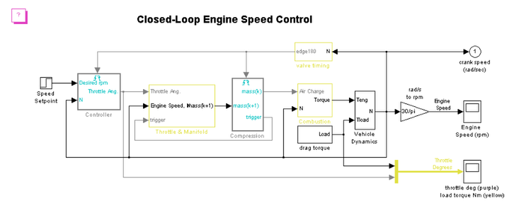
This demonstration shows how to use Triggered Subsystems to model engine timing, including a feedback controller. Different subsystems in the diagram model the mathematical representation of various automotive systems, including the following:
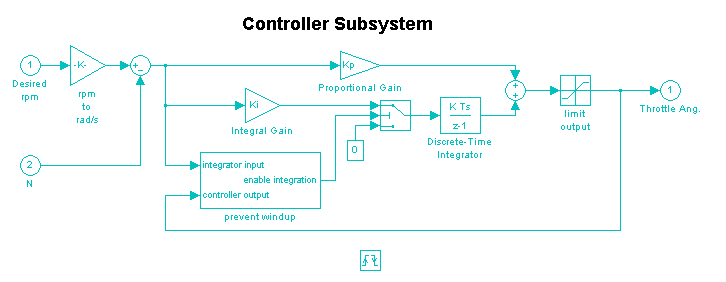
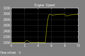
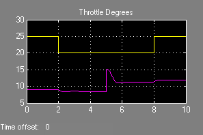
The valve timing subsystem generates a signal that triggers the Controller and Compression subsystems twice per revolution of the crank (calculated from the crank speed.) A speed set point (in rpm) from the Step block drives the simulation. The controller calculates the necessary throttle angle based on the desired rpm and the crank speed that is calculated by the vehicle dynamics. After you run the simulation, the Scopes show the engine speed and the throttle angle compared to the load torque.
A detailed review of the equations used in this design can be found in the white paper Using Simulink and Stateflow for Automotive Examples. Please note that this paper is based on an older version of Simulink and does not use all the newest block diagramming features in the current version of Simulink.